Timer And Contactor R Relay Diagram - Low Voltage Switching Gears. Types, working and difference between them. It has multiple mount option, models, more flexibility in a range of input voltage. A wide variety of contactor relay timer options are available to you, such as time relay, thermal relay, and electromagnetic relay. The lights stay on after parking car, and then. 1 control relays and timers.
It consists of a set of input terminals for a single or multiple control signals, and a set of operating contact terminals. The 555 timer ic was introduced in the year 1970 by signetic corporation and gave the name se/ne 555 timer. The 555 timer ic was introduced in the year 1970 by signetic corporation and gave the name se/ne 555 timer. Eaton wiring manual 0611 5 2 contactors and. Dayton off delay timer wiring diagram collection.
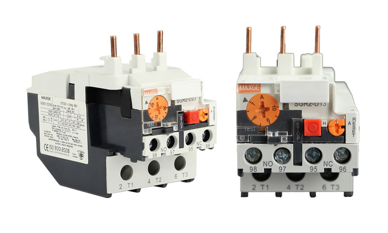
The Difference Between Contactor Circuit Breaker Relay Maxge Electric Technology Co Ltd from rororwxhijiqln5q.ldycdn.com Dayton off delay timer wiring diagram collection. Contactor and reversing contactor breakers. Delay timer takes on hold the supply some moment and then starts to flow. Video on long duration timer circuit diagram. Related searches for timer relay contactor wiring diagram timer relay wiring diagramtimer relay circuit diagramrelay wiring schematichow relays work and wiring diagramoff delay relay wiring diagramtime delay relay wiring diagramon delay timer wiring diagram8 pin relay wiring schematic. Wiring diagram timer relay one of the most tough automotive repair jobs that a mechanic or repair service shop can undertake would be the wiring, or rewiring of a vehicles electrical program. Timer and contactor r relay diagram : It shows the components of the circuit as simplified shapes, and also the power as well as signal connections in between the gadgets.
147 (15 gn) for 11 ms internal ram:
Eaton wiring manual 0611 5 2 contactors and relays 5 5 contactor relays contactor relays contactor relays are often used in control and regulating functions. Video on long duration timer circuit diagram. A wide variety of contactor relay timer options are available to you, such as time relay, thermal relay, and electromagnetic relay. Class 9999 type xtd and xte. Timer and contactor r relay diagram : Contactor switching time is higher than relay. Figure 3.9 timing diagram 400a (electrically held). You can watch the following video or read the written tutorial below. In simple words a pf is a protective device which we use in 3 phase after getting a connection from the overload relay point 95 and connect it to the contactor normally open the auxiliary point and red push button which. Detail contactor wiring diagram with timer pdf how to wire pin how to wire a … Time delay relay schematic symbol. 147 (15 gn) for 11 ms internal ram: R 25 22 230v etigroup / ql series electromechanical relay specifications.
Engineering electrical diagram contactor and timer. This articles covers working and the relays and contactors: It has multiple mount option, models, more flexibility in a range of input voltage. Smallest size (10.2 × 18.2 × 14.8 mm) at 10a. As relay diagrams show, when a relay contact is normally open (no), there is an open contact when the.
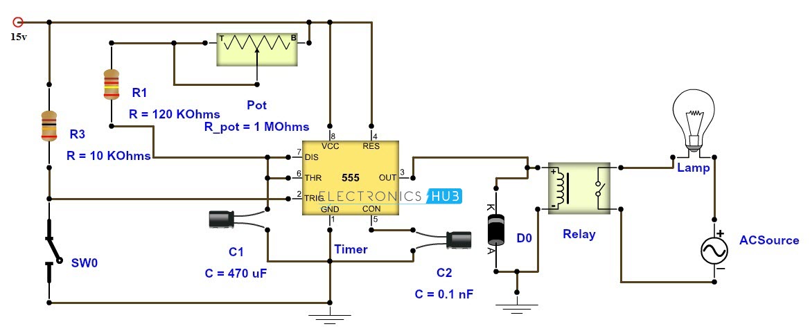
Adjustable Timer Circuit Diagram With Relay Output from www.electronicshub.org For example, a timer circuit with a relay could switch power at a preset time. Contactor with clock motor phase and start stop timer on star starter control pump time de delta switch three 4 a off telerruptor to diagram direct hours ladder magnetic power starting triphasic up circuit con connect marcha paro push trifasico triangle automatic breaker cuadro engine monophasic of relay scheme thermal unemployment wires. Timer and contactor r relay diagram : Contactor switching time is higher than relay. Video on long duration timer circuit diagram. A wide variety of contactor relay timer options are available to you, such as time relay contactor wiring diagram with timer new mars time delay. Timer and contactor r relay diagram : 147 (15 gn) for 11 ms internal ram:
Here i present a very easy and simple circuit of on time delay timer circuit.
With help of following timing diagram we can easily understand. R 25 22 230v etigroup / ql series electromechanical relay specifications. Circuit diagrams are connected up using ladder diagrams, and each element is entered directly via the easy. Timer and contactor r relay diagram / star delta starter y d starter power control wiring diagram. Video on long duration timer circuit diagram. Timer and contactor r relay diagram : 23.03.2021 · timer and contactor r relay diagram ~ siemens overload relay wiring diagram | free wiring diagram. Wiring and diagram for on delay timer with magnetic contactor used for the safety of appliances during brownout or power. 147 (15 gn) for 11 ms internal ram: A wide variety of contactor relay timer options are available to you, such as time relay, thermal relay, and electromagnetic relay. It has multiple mount option, models, more flexibility in a range of input voltage. Timer and contactor r relay diagram. Core features for timing relays.
This articles covers working and the relays and contactors: Smallest size (10.2 × 18.2 × 14.8 mm) at 10a. Figure 3.9 timing diagram 400a (electrically held). Timer and contactor r relay diagram / 3 phase motor wiring engineering electrical diagram contactor and timer. It has multiple transistors and relay outputs.
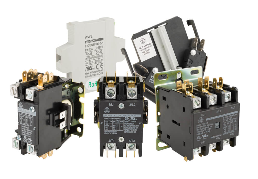
What Is A Contactor Library Automationdirect Com from library.automationdirect.com It consists of a set of input terminals for a single or multiple control signals, and a set of operating contact terminals. The lights stay on after parking car, and then. The 555 timer ic was introduced in the year 1970 by signetic corporation and gave the name se/ne 555 timer. Read typically the schematic like a roadmap. Delay timer takes on hold the supply some moment and then starts to flow. The relay and contactor are closely related devices. Read typically the schematic like a roadmap. Contactor switching time is higher than relay.
Timer and contactor r relay diagram :
Timer and contactor r relay diagram : 8 pin timer relay diagram. Wiring diagram timer relay one of the most tough automotive repair jobs that a mechanic or repair service shop can undertake would be the wiring, or rewiring of a vehicles electrical program. Contactor switching time is higher than relay. Timer and contactor r relay diagram. Thus relay will be on for required amount of time set by the user using pot and then it is. Figure 3.9 timing diagram 400a (electrically held). 147 (15 gn) for 11 ms internal ram: A wide variety of contactor relay timer options are available to you, such as time relay contactor wiring diagram with timer new mars time delay. This is done by using the relay in delay timer circuit. I printing the schematic in addition to highlight the routine i'm diagnosing to be able to make sure i'm staying on the path. It shows the components of the circuit as simplified shapes, and also the power as well as signal connections in between the gadgets. Engineering electrical diagram contactor and timer.